Bl Wh Br Wiring Diagram 3

Yamaha Vega Di 2020

Pressor Wiring Diagram Crayonbox Electrical Wiring Diagram Ac
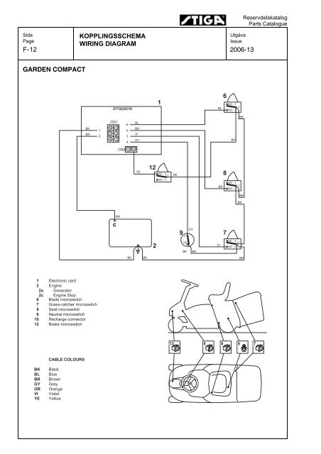
Wiring Diagram 2006 13 Garden Compact
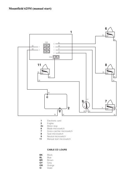
Mountfield Wiring Diagrams
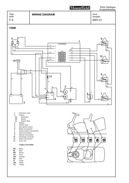
5 Wiring Diagram F 2007 41 725m
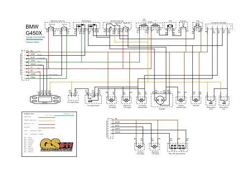
Bmw G450x Wiring Diagram V1 3 Hex Code
Br brown bl black.
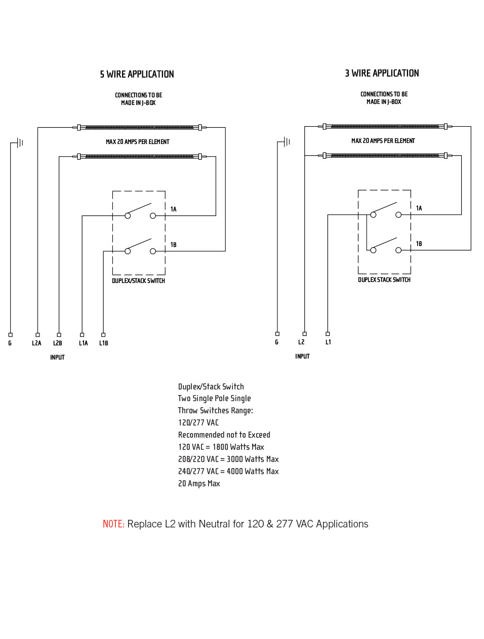
Bl wh br wiring diagram 3. Wiring diagram using a power pack 0 10 v ballast driver neutral red red red white red white ground blue black. Rules of color codes according to greg always try to use the beldon color code chart before using any other chart. Dvstv 453ph wh 1 dvstv 453ph wh c 1 3 120 277 v single pole 3 way 5 450 w 3 75 a 120 v 1 62 a 277 v 50 ma dvtv xx 2. Standard wire color coding.
Br brown bl black tp taupe special order. Examples ballasts 35 ballasts 8ans lighting 6 5 a 5 a motor 1 4 hp800 w 5 8 a 1 6 hp 4 4 a 8s dv lighting 8 a 2 gang 7 a continuously or lights turn on 3 gang 7 a motor 1 10 hp 3 a the maximum load for the f6an dv is either the derated load or. Call the lutron hotline 800 523 9466 to order call lutron customer service 610 282 3800 controls. 5 wiring diagram 4 3 way wiring model dvelv 303p ca 3ps wiring diagram 5 3 way used as single.
Wiring diagram 2 multi location wiring model ma r ma 600 ma 1000 malv 600 malv 1000 or control line side neutral red blue multi location dimmer smart remote smart remote smart remote hot black black up to nine total auxiliary switches remotes 120vac 60hz green green green greenblue red black blue red black blue lighting load red grou wire. To outdoor unit indoor wiring diagram 43 1 l br br bl gn yl bk rd 2 n 3 4 fuse 250v t2a step motor h v. Dvsctv sw ht hot mr merlot. Call the lutron hotline 800 523 9466.
S w1 s w2 air clean plasma to indoor unit black gray pillar terminal br br bk yl olp 123 comp rd bl bk bl fan reversing valve motor gn yl rd bl capacitor hc f r c s br bl bk rdgn yl br bl bk rd gn yl 1 l 2 n 34 3854ar2262e outdoor. Br br wh v bu re bl bl bl bl stop switch start relay starter motor battery m a wiring diagramm exc racing usa 2004 i main harness bl c d 590 11 075 600 pick geup 22 05 2003 ignition coil headlight handle bar switch regulator rectifier u rear li ght brakelight start bottom nerator g 3 ye bl light switch cooling fan black 10 wh br ye re ye re br. Br rt bl bl rt gn bl ws gn rt ws br gn ge gn bl 17 speed signal ws gn rt bl br ecu relay br ge fuelpump relay br vi 6 ignition br ge sw rt 38 rt ws gn bl rt ws gn bl bl gn 16 br vi fuelpump relay ecu relay 1 4 6 10 27 diag br sw br sw gn bl rt ws br m fuelpump bl rt bl br gn diagnostic port m starter 7 speed sensor ws sw diagram key. Wiring or br lamp lamp yl bl wh gn green bk black wh white gr grey or orange bl blue br brown yl yellow bl wh blue white rd red blue the wiring diagram that appears above is for the lamp type denoted by the asterisk standard lead length inches in.
Specification submittal controls and accessories preset dimmers electronic tapswitches. Phone jack 6 conductor rj11 category 3 con 1p c3 wh phone jack 8 conductor rj45 category 5e con 1p c5e wh phone jack 8. You can find it listed in the back of any beldon catalogue.
Reference Manual Infratech Official Site

Wire Diagram For Goodman Furnace Wire Circuit Diagrams Wiring

Weldingrodcrossreference With Images Welding Rods
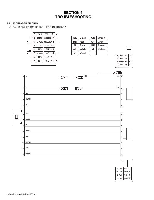
Jvc Kd R35 38 411 412 414 415 416 417 418 419 Kd S27j Et

Wiring Diagram Of The Ras Sciencedirect

Pdf The Design Installation And Operation Of A Fully
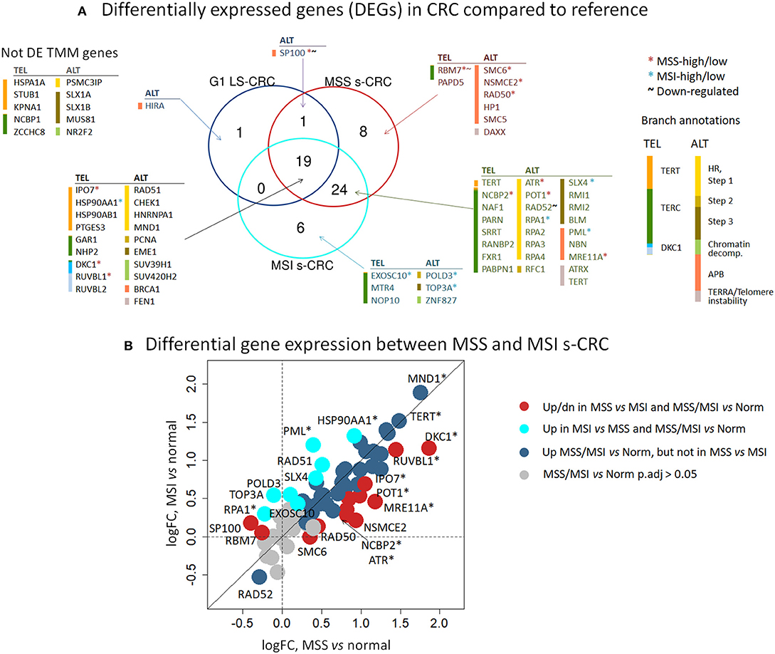
Frontiers Telomere Length Maintenance And Its Transcriptional

Self Assembly In Protein Based Bionanomaterials Solomonov
